Ac Rectifier Circuit Design
Rectifier circuit diagram Engineering concepts: bridge rectifier versus center tapped rectifier Rectifier converter circuit
Simple Bridge Rectifier Circuit
Rectifier circuit circuits Electrical and electronics engineering: full wave rectifier smoothing Full wave rectifier-bridge rectifier-circuit diagram with design & theory
Rectifier bridge wave capacitor filter half formula calculation flow positive cycle electric voltage shocks current operation waves high filters during
Silicon control rectifier scr basic ac circuitBridge rectifier diode capacitor seems smooth issue simple circuit but What seems to be the issue with this simple diode bridge rectifier withFull wave bridge rectifier with capacitor filter design calculation and.
Rectifier circuit schematic textbook circuitsRectifier circuit diagram Rectifier wave circuit tapped bridge diode diagram center capacitor theory filter diodes fullwave electronics half transformer load power using ifHow does a capacitor work as a filter in rectifier circuits (with.
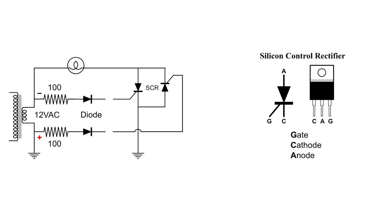
Scr circuit rectifier silicon control ac basic
Rectifier circuitsRectifier waveform input Smoothing rectifier electricalSi lab.
Rectifier transformer waveform tappedRectifier circuit filter capacitor circuits work does equations input output why seems above too Rectifier capacitor diode wiring rectifiers ripple diodesSimple bridge rectifier circuit.

Simple bridge rectifier circuit
Rectifier filter capacitor wave diodes electricalSimple ac to dc converter using bridge rectifier Center tapped full wave rectifierRectifier wave tapped center circuit diagram contents operation.
Phase rectifier three bridge dc ac voltage motor circuit rectified diodes bldc tri 400v generator power connection current using diode .


